Today I am build a DIY light with parts supplied by Northern Growlights/Photon Labs LLC.
Www.northerngrowlights.com. Northern Growlights recently went into business selling COB based LED growlights. They also are selling parts to build your own light. Even better, they designed a custom frame you can use with your parts if you wish! I like the frame design, so I bought it to build the parts I'm testing on it.
SAFETY, FIRST, LAST, AND ALWAYS! Not only will you be using tools, but your working with electricity. Electricity demands caution on your part. Mistakes/accidents can be fatal!
NEVER work on your project with it plugged in.
Check all connections twice
When working with DC current, double check the polarity, (+) positive, (-) negative of your connections.
Never bring liquids into your work area
Check your tools are in working condition.
You get the idea. Think the entire project through before you begin.
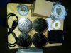
Parts from Northern Growlights:
4x SST120 Pin Heatsink
4x Glass lens
4x Citizen CLU058 1825
4x Ideal holder
Assorted screws
..................................................................
Northern Growlights does not currently sell drivers so I ordered mine online at: www.mouser.com
I selected the Meanwell HLG-240H-C2100b so that I may drive the cobs harder later on, if I so wish.
Here are the specs:

I need 2 drivers as My cobs operate at around 50 volts at 1400 milliamp so I can run 2 on this driver at even the maximum amperage. I'll be running at this level as it is a good balance of efficiency and light output. I think the chip runs at about 47% efficiency at 1400ma.
I also needed for this build:
18gauge solid core wire – 25 ft.
Wago wire connectors 15
heatshrink tubing
Artic Alumina heatsink compound
1/2”x3/16” screws I bought 10
1/4” Acorn nuts -6 – just because they look nice!
1/4” domehead screws 6
3/16” flat washers – 10
rubber gloves – helps keep things clean
70% isopropyl alcohol
colored electrical tape red and black
100k potentiometer – 2
knob for the potentiometer 2
I need 2 drivers as My cobs operate at around 50 volts at 1400 milliamp so I can run only 2 on one driver at even the maximum amperage.

I'll be running at 1400ma as it is a good balance of efficiency and light output. I think the chip runs at about 47% efficiency at 1400ma.
I also needed for this build:
18gauge solid core wire – 25 ft.
Wago wire connectors 15
heatshrink tubing
Artic Alumina heatsink compound
1/2”x3/16” screws I bought 10
1/4” Acorn nuts -6 – just because they look nice!
1/4” domehead screws 6
3/16” flat washers – 10
rubber gloves – helps keep things clean
70% isopropyl alcohol
colored electrical tape red and black
100k potentiometer – 2
knob for the potentiometer 2
Amp gauge ( optional but nice to have )
aluminum project box
plastic project box
3/8” grommets – 2
Tools and other parts needed:
Three Phillips screwdrivers
2 flat blade screwdrivers
Cordless drill
drill bits
small metal files
any lightweight chain for a safety chain
rope ratchet light hangers ( or what your prefer )
tape measure
adjustable wrench or pliers

Assembly
I started with the Mod420 frame. I drilled the existing holes used to connect the frame sections to 1/4” and used the 1/4” screws and acorn nuts to join them. The acorn nuts were used on the LED side of the frame, just because I thought it made it look nice.

With the frame assembled I mounted the COBs to the heatsinks
First I screwed the cob holder screws into the heatsink to be sure the threads were good. Don't just assume they are........ and screw them all the way in to test all the threads in the hole. I only screwed the lens holder screws in a few threads and........it wasn't fun to fix! More on that later.
After checking ALL the proper threaded holes. I mounted the Citizen CLU058 18125 COBs in the holders. The can only go in one way with this holder and chip. Don't force it. If it doesn't want to snap in, you may have not matched the + on the chip to the + on the holder.

Take an empty COB holder and place it on the heatsink and identify which holes fit your chips holder, there are several sets of screw
holes for various COBs on the heatsink. Note their position relative to the channel in the heatsink the pass wire through.
Once the chip is seated put on rubber gloves. I don't care how little thermal grease you use, you WILL get it on you....
I built custom pcs for my customers when I had my business. We did some with serious overclocking. When you overclock a 3Ghz chip to almost 4.2 Gzh, your cpu is cranking out some serious heat! Watercooling was a must.
And so was the proper application of thermal compound. My “thick” coating is much thinner than most people's idea of a thin coating. The purpose of thermal compound is to fill the the pits in the mating surfaces. It is not meant to be THE thermal interface, only to even up the surfaces.
I usually apply the grease by placing a few tiny dabs in the chip's thermal interface. I then smear it all over the surface as evenly as I can. The coating should be so thing you can see through it. I usually then scrape the surface flat with a single edge razor blade as a straight edge. This will give you the thinnest coating. Do the same on the heatsink. If the coating on either looks even marginally thicker in places, you need to use thermal pads instead. Thermal grease should never be used to fill in low spots or uneven surfaces.
I left the coating the way it was after spreading with my finger. I replaced my rubber gloves with clean ones. I then fit one screw in the holder and use it to line up the holes in the heatsink and screw it in loosely. Screw in the second screw till just snug. Snug the other screw a little tighter, then the same for the last screw. Careful, don't over tighten! Do these steps for all your cob/heatsink.

Cut enough lengths of 18 gauge wire to reach from the chip itself to your junction box where the wires will join and be connected. With my frame, I cut 24” lengths. Wire each COB holder. If your using twin lead wire strip about 8” of outer insulation. Strip about 3/8” of insulation from each wire. Feed the not stripped end through the heatsink wire channel from the bottom. On the side on the BJB type holders that I'm using, are little spring loaded holes. Push the stripped red wire into the + hole then the white or black, depending on your wire into the negative. This may seem contrary to other builds you may have seen. Explanation later. Fit the wire tight to the sides on the cob holder to keep it neat. Pull the wire from the pin side of the heatsink till the wires are snug against the holder.
Mount the heatsinks in the frame. I stood my heatsinks COB side up on my bench, then rested the frame over the heatsinks. I lined up the mounting holes and put a screw in each heatsink to hold them in place. This will help you line up the holes in the lens retaining ring with the frame/heatsink holes. These screws are the same ones that hold the heatsink to the frame.

This is the aggravating part of the build.. mounting the silicone gaskets on the lenses! Not that there is a thick and a thin lip on the gasket. Then thin lips faces outward, the thick lip faces the heatsink. Place the lenses in the retainer rings. Remove the screw from the frame and heatsink. Line the hole up in the heatsink with the mounting holes in the frame and the lens ring. Start one screw. Screw it down about ½ way, then install the rest of the screws. Snug them tight. Repeat for all heatsinks.
One of the screw holes had metal scrap or something about ½ way done the hole. The screw became hard to screw any further. I stopped rather than force it and tried to back it out. It wouldn't budge.. I finally removes it by gripping the shaft of the screw ( thankfully there was still a 1/4” above the ring ) very tightly and slowly turning the screw to back it out. I got lucky, it came loose after a few turns. I put in a new screw and it was fine.


I wire mine a little different from what I commonly see. I want the wiring to be easy to access if I want to do repairs or upgrades. I wire by wiring each cob then running all those wires to a junction box. I then use Wago connectors to join the cobs in series connections, positive (+) to negative (-) Start by connecting the driver's negative wire to the first COB's negative wire. Then the cob's positive wire to the negative wire of the next COB. Continue doing the same if you have more than 2 cobs. Be sure you understand how many cobs you can have in one string. I'm limited by the voltage rating of the cob holders. My chips run at an average of 50 volts. The cob holder is only rated for 150 volts maximum, so I'm running 2 cobs per driver.
Connect the positive wire of the last cob to the positive wire from the driver.
Next you get to try your hand at soldering! You'll need to solder wire and/or a resistor to the potentiometer. The resistor is optional, I use it to prevent the driver from running over spec. I used a 10k resistor which I soldered to one leg of the pot. When you solder wires on you use only the center post and either the left or right post. Most use the right post as then the knob turns to the right to increase power. Mount your potentiometer in whatever you plant to mount it in. I won't go into detail about soldering, its a subject worthy of its own post.
I decided to mount my drivers remotely to keep weight of the light and heat from the tent. I mounted them to a scrap of plywood I had that was perfect for the job. I screwed the drivers and three junction boxes to the board also.
I fed the power to cob wires into one box, and the dimmer wires into another, then the led power wires into the third junction box.
Installed the dimmer into a blank cover I drilled a 1/” hole thru. I connected the positive wire to the center pot of the pot, and the negative wire to the right side post. All wires connections completed with Wago connectors.


On the bottom, I ran the power cables from the driver into a junction box. I connected the 2 red (+) wires to one wago connector, and the two black wires (-), to the other. I then inserted into the box, the 12ft. Power cord I made as the supplied cable was too short for my needs.
About the Wago connectors. I really like them! You need to lift the little levers all the way up before inserting wires. The lever pinches the connection tight when you put the lever back down.
I connected 7.5' of 16ga. wire from the each driver to the junction box on the light. Gives me plenty of extra for light adjustment, etc, without meaningful losses to wire resistance. Connect the positive wire from the driver to the positive end of the cob at the end of the string. Connect the negative wire to the negative at the other end of the string. Your circuit is now complete. TRIPLE check all connections!
And right away........ it didn't work! Now we put the volt/ohm meter to work. I used short scraps of wire inserted into the wago on the positive and negative led power wires I used these leads to test for voltage. With all other wiring disconnected, test for voltage at the driver. Disconnect the power cord from the outlet. Then re-connect the wires the run to the lightson the driver end. Disconnect those same wires from the box on the light. Tape them to your meter's probes ( for safety ) plug the power cord into an outlet and check for voltage. By this method I found I didn't have good connection in the wago connectors on the 16 gauge stranded wire. You need to be sure the wire seated into connector all the way. Once my connections were corrected, I re-connected the power wires to the cobs.
Three........Two....... One........ We have Light!

These lights are bright. No, no, you don't understand, these lights are BRIGHT!!! I think they bleached my ceiling...lol! The pic is with the dimmer turned down all the way..... Ohh yeah! THAT'S what I wanted!
Final thoughts and comments.
This was not an easy project but it was very satisfying to complete it and see it work! I have many hours invested in this. Some of that time was the way I decided to wire the light. Some of that time was my stopping and pondering what and how I'd do next. Some of it was trips to town for materials I needed. And a good portion of it was checking and re-checking that all was wired properly. Patience pays in a build like this.
And its not a quick project no matter how you approach it, at least not the first time.
Did I mention it was bright??
I like the 3500k light, hopefully my plants will too.
All parts supplied by Northen Growlights/Photon Labs LLC met all expectations. The issue with the heatsink threads is not in any way, a flaw in the heatsink. It was machining residue the was caught in the threads. Always pays to check things like this.
The Glass lenses appear to be well made. They are very heavy. Glad I decided to remote my drivers as the 2 drivers would have added quite a bit more weight to the light. I didn't weight them but I bet they add about 10 pounds! The heatsinks are well machined and thew anodized coating is even and well applied.
More than enough screws for mounting the cob holders and the light engines and lenses to the frame.
The frame is very nice also! I'm quite pleased with it. I made small modifications that were purely cosmetic. A couple of the mounting slots for the heatsinks needed a quick touch with a rattail file, but just a few strokes to lengthen the slot very slightly for screw clearance. If you buy one, be warned there are a lot of sharp edges and you should file/sand them to prevent a nasty cut!
Thank you to all involved in making this build happen, and a big thank you to Northern Growlights! I can't wait to put this over a plant and bath her in some awesome light!
Www.northerngrowlights.com. Northern Growlights recently went into business selling COB based LED growlights. They also are selling parts to build your own light. Even better, they designed a custom frame you can use with your parts if you wish! I like the frame design, so I bought it to build the parts I'm testing on it.
SAFETY, FIRST, LAST, AND ALWAYS! Not only will you be using tools, but your working with electricity. Electricity demands caution on your part. Mistakes/accidents can be fatal!
NEVER work on your project with it plugged in.
Check all connections twice
When working with DC current, double check the polarity, (+) positive, (-) negative of your connections.
Never bring liquids into your work area
Check your tools are in working condition.
You get the idea. Think the entire project through before you begin.
Parts from Northern Growlights:
4x SST120 Pin Heatsink
4x Glass lens
4x Citizen CLU058 1825
4x Ideal holder
Assorted screws
..................................................................
Northern Growlights does not currently sell drivers so I ordered mine online at: www.mouser.com
I selected the Meanwell HLG-240H-C2100b so that I may drive the cobs harder later on, if I so wish.
Here are the specs:
I need 2 drivers as My cobs operate at around 50 volts at 1400 milliamp so I can run 2 on this driver at even the maximum amperage. I'll be running at this level as it is a good balance of efficiency and light output. I think the chip runs at about 47% efficiency at 1400ma.
I also needed for this build:
18gauge solid core wire – 25 ft.
Wago wire connectors 15
heatshrink tubing
Artic Alumina heatsink compound
1/2”x3/16” screws I bought 10
1/4” Acorn nuts -6 – just because they look nice!
1/4” domehead screws 6
3/16” flat washers – 10
rubber gloves – helps keep things clean
70% isopropyl alcohol
colored electrical tape red and black
100k potentiometer – 2
knob for the potentiometer 2
I need 2 drivers as My cobs operate at around 50 volts at 1400 milliamp so I can run only 2 on one driver at even the maximum amperage.
I'll be running at 1400ma as it is a good balance of efficiency and light output. I think the chip runs at about 47% efficiency at 1400ma.
I also needed for this build:
18gauge solid core wire – 25 ft.
Wago wire connectors 15
heatshrink tubing
Artic Alumina heatsink compound
1/2”x3/16” screws I bought 10
1/4” Acorn nuts -6 – just because they look nice!
1/4” domehead screws 6
3/16” flat washers – 10
rubber gloves – helps keep things clean
70% isopropyl alcohol
colored electrical tape red and black
100k potentiometer – 2
knob for the potentiometer 2
Amp gauge ( optional but nice to have )
aluminum project box
plastic project box
3/8” grommets – 2
Tools and other parts needed:
Three Phillips screwdrivers
2 flat blade screwdrivers
Cordless drill
drill bits
small metal files
any lightweight chain for a safety chain
rope ratchet light hangers ( or what your prefer )
tape measure
adjustable wrench or pliers
Assembly
I started with the Mod420 frame. I drilled the existing holes used to connect the frame sections to 1/4” and used the 1/4” screws and acorn nuts to join them. The acorn nuts were used on the LED side of the frame, just because I thought it made it look nice.
With the frame assembled I mounted the COBs to the heatsinks
First I screwed the cob holder screws into the heatsink to be sure the threads were good. Don't just assume they are........ and screw them all the way in to test all the threads in the hole. I only screwed the lens holder screws in a few threads and........it wasn't fun to fix! More on that later.
After checking ALL the proper threaded holes. I mounted the Citizen CLU058 18125 COBs in the holders. The can only go in one way with this holder and chip. Don't force it. If it doesn't want to snap in, you may have not matched the + on the chip to the + on the holder.
Take an empty COB holder and place it on the heatsink and identify which holes fit your chips holder, there are several sets of screw
holes for various COBs on the heatsink. Note their position relative to the channel in the heatsink the pass wire through.
Once the chip is seated put on rubber gloves. I don't care how little thermal grease you use, you WILL get it on you....
I built custom pcs for my customers when I had my business. We did some with serious overclocking. When you overclock a 3Ghz chip to almost 4.2 Gzh, your cpu is cranking out some serious heat! Watercooling was a must.
And so was the proper application of thermal compound. My “thick” coating is much thinner than most people's idea of a thin coating. The purpose of thermal compound is to fill the the pits in the mating surfaces. It is not meant to be THE thermal interface, only to even up the surfaces.
I usually apply the grease by placing a few tiny dabs in the chip's thermal interface. I then smear it all over the surface as evenly as I can. The coating should be so thing you can see through it. I usually then scrape the surface flat with a single edge razor blade as a straight edge. This will give you the thinnest coating. Do the same on the heatsink. If the coating on either looks even marginally thicker in places, you need to use thermal pads instead. Thermal grease should never be used to fill in low spots or uneven surfaces.
I left the coating the way it was after spreading with my finger. I replaced my rubber gloves with clean ones. I then fit one screw in the holder and use it to line up the holes in the heatsink and screw it in loosely. Screw in the second screw till just snug. Snug the other screw a little tighter, then the same for the last screw. Careful, don't over tighten! Do these steps for all your cob/heatsink.
Cut enough lengths of 18 gauge wire to reach from the chip itself to your junction box where the wires will join and be connected. With my frame, I cut 24” lengths. Wire each COB holder. If your using twin lead wire strip about 8” of outer insulation. Strip about 3/8” of insulation from each wire. Feed the not stripped end through the heatsink wire channel from the bottom. On the side on the BJB type holders that I'm using, are little spring loaded holes. Push the stripped red wire into the + hole then the white or black, depending on your wire into the negative. This may seem contrary to other builds you may have seen. Explanation later. Fit the wire tight to the sides on the cob holder to keep it neat. Pull the wire from the pin side of the heatsink till the wires are snug against the holder.
Mount the heatsinks in the frame. I stood my heatsinks COB side up on my bench, then rested the frame over the heatsinks. I lined up the mounting holes and put a screw in each heatsink to hold them in place. This will help you line up the holes in the lens retaining ring with the frame/heatsink holes. These screws are the same ones that hold the heatsink to the frame.
This is the aggravating part of the build.. mounting the silicone gaskets on the lenses! Not that there is a thick and a thin lip on the gasket. Then thin lips faces outward, the thick lip faces the heatsink. Place the lenses in the retainer rings. Remove the screw from the frame and heatsink. Line the hole up in the heatsink with the mounting holes in the frame and the lens ring. Start one screw. Screw it down about ½ way, then install the rest of the screws. Snug them tight. Repeat for all heatsinks.
One of the screw holes had metal scrap or something about ½ way done the hole. The screw became hard to screw any further. I stopped rather than force it and tried to back it out. It wouldn't budge.. I finally removes it by gripping the shaft of the screw ( thankfully there was still a 1/4” above the ring ) very tightly and slowly turning the screw to back it out. I got lucky, it came loose after a few turns. I put in a new screw and it was fine.
I wire mine a little different from what I commonly see. I want the wiring to be easy to access if I want to do repairs or upgrades. I wire by wiring each cob then running all those wires to a junction box. I then use Wago connectors to join the cobs in series connections, positive (+) to negative (-) Start by connecting the driver's negative wire to the first COB's negative wire. Then the cob's positive wire to the negative wire of the next COB. Continue doing the same if you have more than 2 cobs. Be sure you understand how many cobs you can have in one string. I'm limited by the voltage rating of the cob holders. My chips run at an average of 50 volts. The cob holder is only rated for 150 volts maximum, so I'm running 2 cobs per driver.
Connect the positive wire of the last cob to the positive wire from the driver.
Next you get to try your hand at soldering! You'll need to solder wire and/or a resistor to the potentiometer. The resistor is optional, I use it to prevent the driver from running over spec. I used a 10k resistor which I soldered to one leg of the pot. When you solder wires on you use only the center post and either the left or right post. Most use the right post as then the knob turns to the right to increase power. Mount your potentiometer in whatever you plant to mount it in. I won't go into detail about soldering, its a subject worthy of its own post.
I decided to mount my drivers remotely to keep weight of the light and heat from the tent. I mounted them to a scrap of plywood I had that was perfect for the job. I screwed the drivers and three junction boxes to the board also.
I fed the power to cob wires into one box, and the dimmer wires into another, then the led power wires into the third junction box.
Installed the dimmer into a blank cover I drilled a 1/” hole thru. I connected the positive wire to the center pot of the pot, and the negative wire to the right side post. All wires connections completed with Wago connectors.
On the bottom, I ran the power cables from the driver into a junction box. I connected the 2 red (+) wires to one wago connector, and the two black wires (-), to the other. I then inserted into the box, the 12ft. Power cord I made as the supplied cable was too short for my needs.
About the Wago connectors. I really like them! You need to lift the little levers all the way up before inserting wires. The lever pinches the connection tight when you put the lever back down.
I connected 7.5' of 16ga. wire from the each driver to the junction box on the light. Gives me plenty of extra for light adjustment, etc, without meaningful losses to wire resistance. Connect the positive wire from the driver to the positive end of the cob at the end of the string. Connect the negative wire to the negative at the other end of the string. Your circuit is now complete. TRIPLE check all connections!
And right away........ it didn't work! Now we put the volt/ohm meter to work. I used short scraps of wire inserted into the wago on the positive and negative led power wires I used these leads to test for voltage. With all other wiring disconnected, test for voltage at the driver. Disconnect the power cord from the outlet. Then re-connect the wires the run to the lightson the driver end. Disconnect those same wires from the box on the light. Tape them to your meter's probes ( for safety ) plug the power cord into an outlet and check for voltage. By this method I found I didn't have good connection in the wago connectors on the 16 gauge stranded wire. You need to be sure the wire seated into connector all the way. Once my connections were corrected, I re-connected the power wires to the cobs.
Three........Two....... One........ We have Light!
These lights are bright. No, no, you don't understand, these lights are BRIGHT!!! I think they bleached my ceiling...lol! The pic is with the dimmer turned down all the way..... Ohh yeah! THAT'S what I wanted!
Final thoughts and comments.
This was not an easy project but it was very satisfying to complete it and see it work! I have many hours invested in this. Some of that time was the way I decided to wire the light. Some of that time was my stopping and pondering what and how I'd do next. Some of it was trips to town for materials I needed. And a good portion of it was checking and re-checking that all was wired properly. Patience pays in a build like this.
And its not a quick project no matter how you approach it, at least not the first time.
Did I mention it was bright??
I like the 3500k light, hopefully my plants will too.
All parts supplied by Northen Growlights/Photon Labs LLC met all expectations. The issue with the heatsink threads is not in any way, a flaw in the heatsink. It was machining residue the was caught in the threads. Always pays to check things like this.
The Glass lenses appear to be well made. They are very heavy. Glad I decided to remote my drivers as the 2 drivers would have added quite a bit more weight to the light. I didn't weight them but I bet they add about 10 pounds! The heatsinks are well machined and thew anodized coating is even and well applied.
More than enough screws for mounting the cob holders and the light engines and lenses to the frame.
The frame is very nice also! I'm quite pleased with it. I made small modifications that were purely cosmetic. A couple of the mounting slots for the heatsinks needed a quick touch with a rattail file, but just a few strokes to lengthen the slot very slightly for screw clearance. If you buy one, be warned there are a lot of sharp edges and you should file/sand them to prevent a nasty cut!
Thank you to all involved in making this build happen, and a big thank you to Northern Growlights! I can't wait to put this over a plant and bath her in some awesome light!